Introduction #
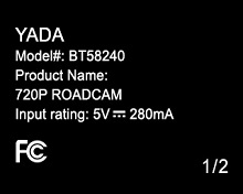
I found this dashcam for $0.50 at a garage sale and picked it up with a teardown in mind. It did not come with the 12V to mini-USB power cable, but it did come with the 4GB MicroSD card. The camera has a maximum resolution of 720p with an option for VGA (640x480). As of this publication, the cameras are available brand new from Walmart for less than $4.
Disassembly #
There are no visible screws on the camera housing. It is instead held together by 6 clips on the sides of the housing.
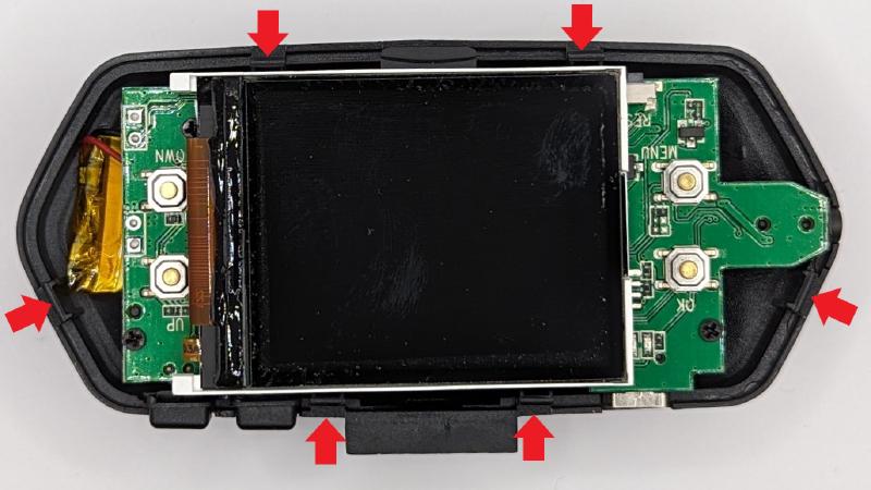
The 2" LCD screen is connected to the main board with a 22-pin FFC connector. There are three pieces of what seems to be double sided tape with one side still having backer paper on it that are placed to support the LCD inside of the housing on top of the PCBA.
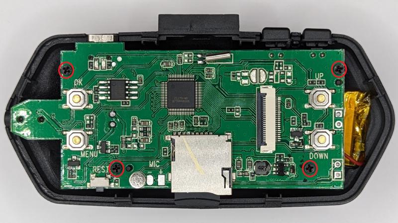
The PCB is secured to the housing with 4 Phillips screws, highlighted in red circles below. Note that this image is rotated 180 degrees from the previous image to allow for the silk screen to be the right way up.
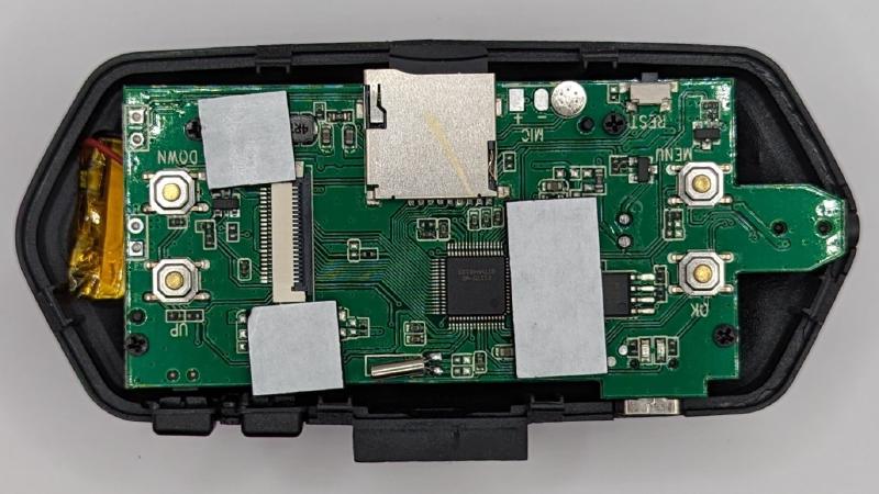
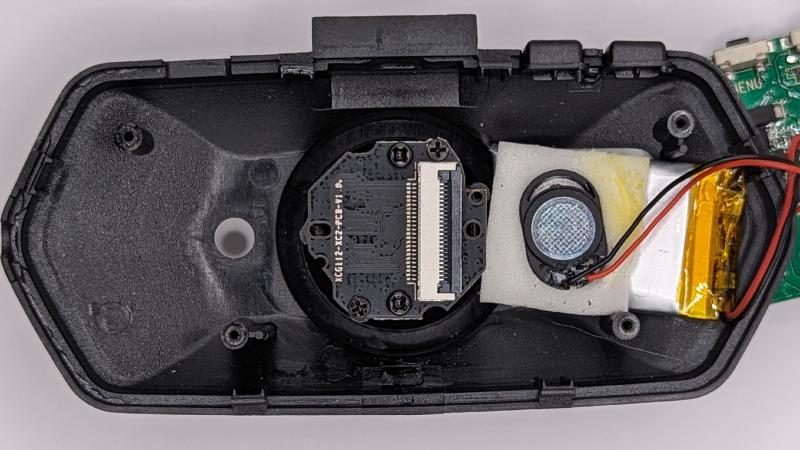
Flipping the PCB over reveals another FFC connector (24-pins), and two sets of two wires for connecting the battery and the speaker.
The battery and the speaker appear to be crammed into the housing with two more pieces of double-sided tape. There are four screws visible on the imager assembly, but only two of them connect the assembly to the housing. The other two connect the lens to the imager assembly.
Major Components #
Microcontroller #
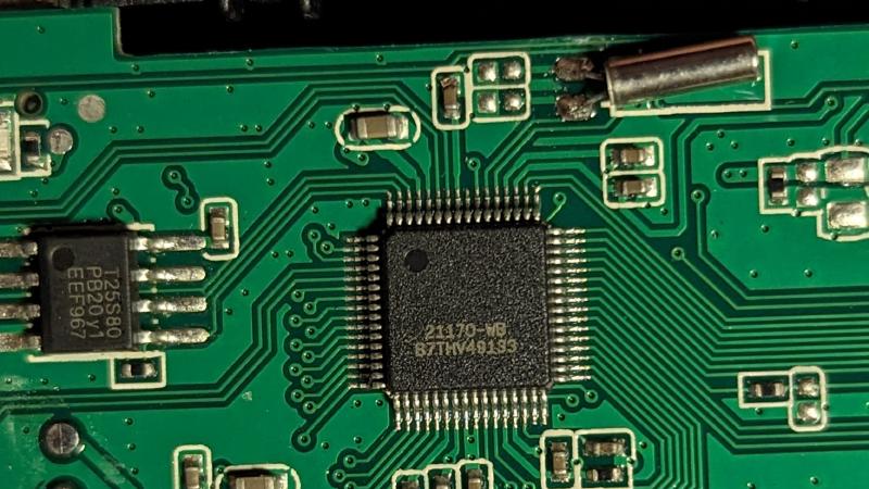
The microcontroller is in a 64-pin QFP package with the following markings:
21170-WB
87THV49133
I am not sure if the trailing B or the leading 8 are correct due to the very fine markings. I have been unable to locate the part online with any permutation or subset of the markings.
SPI Flash #
The SPI flash is in an 8-pin SOP type package. It has markings:
T25S80
PB20y1
EEF967
It is an 8Mbit SPI Flash with a power supply rating of 2.7-3.6V. The Datasheet is currently available from chipsourcetek.com. The part is not directly listed in Xgpro v12.66, but the ID reads as 0x5E3214 and can be read as a GM25Q128A which is supported in Xgpro.
Screen #
The screen is a 224x176 pixel 2" LCD. There is a string in the flash memory for ‘ili9225’ so there is a chance that the ILI9225 controller is either incorporated into the microcontroller or embedded in the screen assembly. On the ribbon cable for the screen, the string ‘TYD2.0LCD122-22PIN’ is present on the silkscreen. Although there are many similar parts online, I cannot locate the exact one.
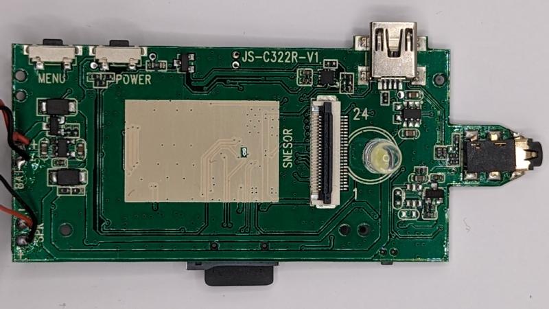
Camera Assembly #
The camera assembly is labeled as XCG112-XC2-PCB-V1.0. It has a 24-pin FFC connector on the assembly. This part does not seem to be available in general distribution. Based on strings from the SPI flash, the image sensor is likely a GC1054 from Galaxy Microelectronics which is a 1/4 Inch, 0.92 MP, CMOS Image Sensor with a frame rate of 30 fps.
Flash Investigation #
After extracting the flash, I investigated its contents with a few different methods. These methods included strings and binwalk. binwalk only identified a few files, all of which were JPEG and TIFF.
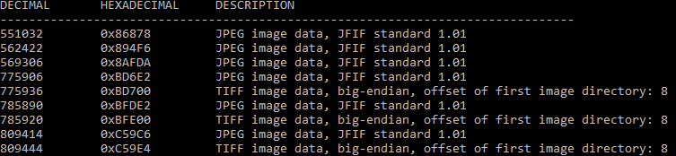
Although I have been unable to get anything from the identified TIFF files, the JPEGs contain splash screens and the information pages that the camera uses. These JPEGs were helpful for checking the screen resolution.
Using strings turns up several interesting items:
| String found | Presumed reference |
|---|---|
| ili9225 | Reference to LCD screen driver |
| JRAK-GC1054-20191225 | Package related to GC1054 image sensor |
| SC7A30E | Potentially an accelerometer |
| DA380 | Unknown |
| GMA301 | Unknown |
| Lavf54.63.104 | Video encoder |
Microcontroller Investigation #
To continue reverse engineering this part, I tried to look up similar Yada branded dashcam information in FCC reports. The exact model I took apart does not have an FCC report because it does not have any intentional wireless functions, but there are variants that have Wi-Fi functionality like the BT58187. Its FCC report can be found here.
Unfortunately for me, the block diagram, operation description, and schematics are all confidential and not available to the public. Internal pictures only include an RF module from iottech that uses an iComm SV6030P on a carrier board with castellated holes. Presumably, there is a primary microcontroller somewhere else in the design but I cannot easily check if it has more informative markings (The idea is that Yada will likely stick to a family of parts so other products they make may be from the same microcontroller family).
Conclusion & Files #
Unfortunately, my inability to figure out the microcontroller is blocking any further process on this reverse engineering project. If you would like to take a stab at it, this archive contains all the pictures shown here along with the binary from the flash.