Introduction #
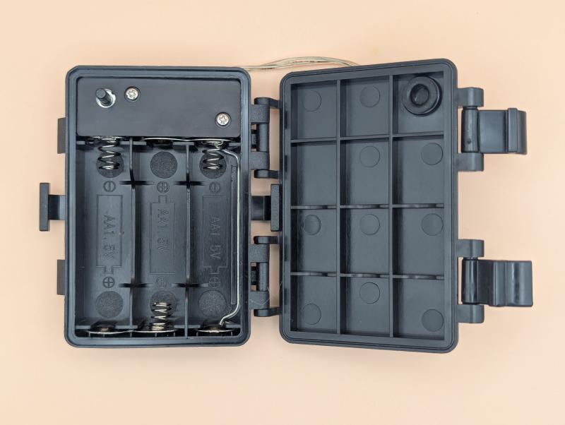
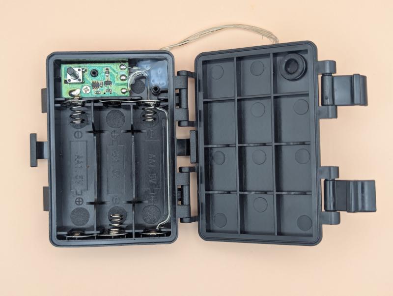
The target of this teardown is a very simple LED controller for a child’s bicycle. I got it as a bonus piece when my wife sourced a bicycle from Facebook Marketplace. Physically the item is a black plastic box with one button and a hard-wired LED string. It is powered by 3 AA batteries in series. There are only three screws between me and getting the PCBA out - two on the cover, and one mounting the PCBA to the case.
The PCBA #
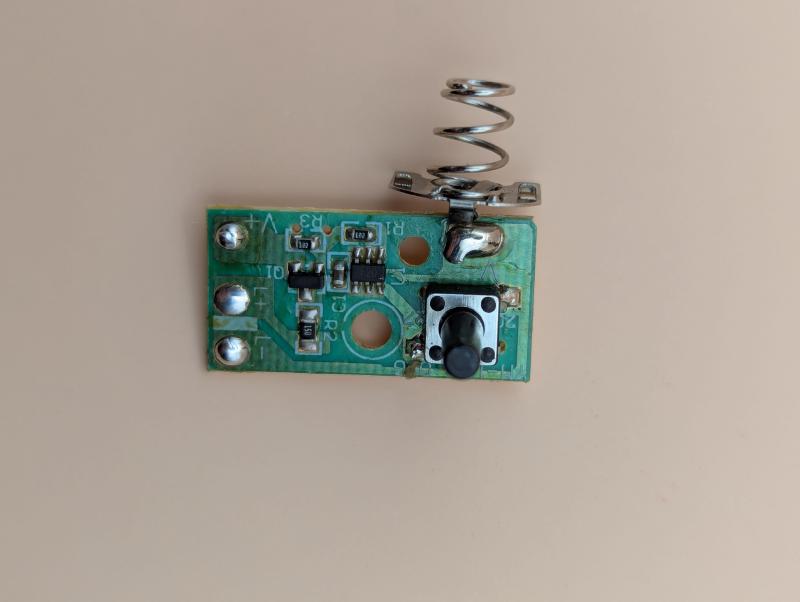
The PCBA is a small and is a single layer layout and assembly. There are only 8 components on the entire thing.
| Item # | Reference | Description |
|---|---|---|
| 1 | V- | Battery Terminal |
| 2 | SW1 | Pushbutton Switch |
| 3 | U1 | Latching Controller |
| 4 | R1 | 1 kΩ Resistor |
| 5 | C1 | 4.7 μF Capacitor |
| 6 | R2 | 15 Ω Resistor |
| 7 | Q1 | PNP Transistor (S8550) |
| 8 | R3 | 1 kΩ Resistor |
The resistors are large enough that the values are written on them, and for C1 I removed it and measured a value around 4 μF. Since most capacitors have wider tolerances (20% is fairly average) my best guess is that the nominal value of it is 4.7 μF.
Q1 and U1 Part Identification #
As usual, identifying ICs based on their physical package and top-side markings is a challenge. In this case, we have a transistor (conveniently identified as Q1) in a SOT-23 package labelled 2TY. Searching for this designator with Grok and regular web search comes up with a possible identification of an S8550 from Shenzhen City Koo Chin Electronics Limited. This is a PNP transistor which would work as a high side driver for our LED chain so it seems suitable.
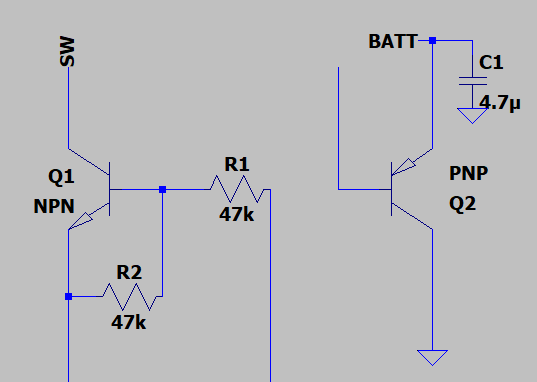
The next part to identify is U1, which is in a SOT-363 package and has the label F20. It needs to latch the state of the output based on button presses so it is likely some sort of flip-flop / application-specific latch IC. Searching for this does not come up with a clear-cut solution. Grok’s initial idea is that it could be a Rohm EMF20 which it clearly can’t be based on the pinout. To get an idea of how nonsensical this solution is, I drew it in LTSpice.
The Circuit and Theory of Operation #
To confirm the expected operation of this product, I used a PCBite probe setup.
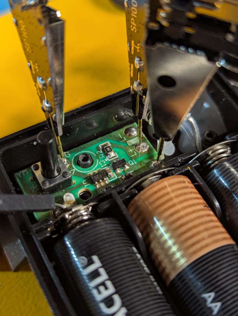
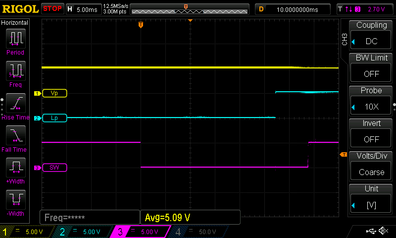
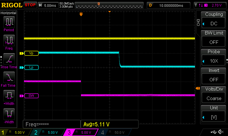
This way I can check exactly how SW1 is biased and check the turn on and turn off timing. The results indicated that U1 does work as a latch and that the SW pin is biased high through U1, and a falling edge on that pin causes a change in the state of the output. It takes about 55ms to turn on and 26ms to turn off.
In the oscilloscope captures below, the signals are labelled:
- Vp for the positive battery net
- Lp for the positive LED output net (other side of Q1)
- SW for the switch pin net that goes to U1
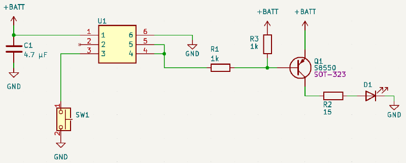
Putting everything together, the circuit for this product is below.